Crippling Under Compressive Loads
In the first article on the subject, we discussed the possible damage scenarios in thin-walled beams. Now, let’s continue to examine these situations one by one. In this article, we will examine the Crippling damage scenario in thin-walled beams under compressive loads.
Static Strength:
Crippling:
In beams exposed to a point compressive load (P) with cross-sectional area A, the axial stress σ = P/A can be found using the equation. This equation is valid until there is a local buckling in any section of the cross-section. To understand more clearly:
If the load is gradually increased after the onset of local buckling, the more rigid areas, i.e., the corners, can resist the applied load, while the buckling regions continue to deform significantly. This situation can continue until the corner regions reach the yield limit (Fe = Fcy) of the material (see Figure-1). Here, the ratio of the load applied to the cross-section of the beam gives us the average crippling stress (Fcc). The average value mentioned here can be at most the yield stress (Fcc ≤ Fcy). In fact, we calculate the ultimate capacity of the beam from here, which is one of the most important damage scenarios that need to be prevented primarily in aircraft structures.
When the cause of the damage scenario is examined more in-depth, it will be seen that the stress that comes to the corner regions is not only axial stress. As the beam ends (flanges) and beam body (web) lose their stability and begin to deform, a sinusoidal twisting moment that varies sinusoidally with larger moments at points that deform more and smaller moments at points that deform less also affects the rigid regions at the corner. The other effect of the same deformations on the corners is a bending moment that also varies sinusoidally, so a variable axial stress distribution will also occur at the corner. Of course, it should not be forgotten that the sinusoidal bending and twisting moments mentioned here are secondary moments and result from the deformations of structures exposed to axial loads in the direction of plane normals.
As a result, all these effects show very clearly that the Crippling event cannot only be revealed with theoretical calculations, but it also needs to be examined with tests when considered together with axial load.
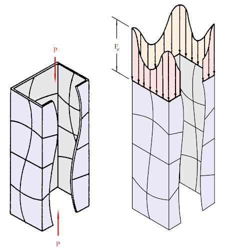
(a) (b)
Figure-1 (a) Load is applied (b) Stress distribution after local buckling
(a) (b)
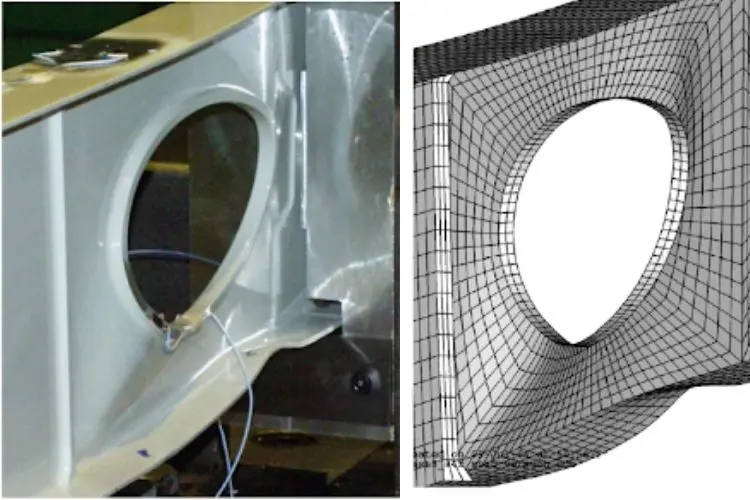
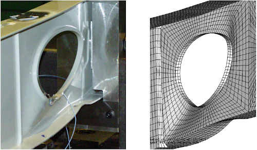
Figure-2 (a) Test result (b) Finite element analysis result
Moreover, there is a stress concentration, albeit local, at the edges of a lightened holed beam, and if this stress is tensile, it triggers fatigue, and if it is compressive, it triggers sudden collapse (see Figure-2). In other words, the edges of the holes and, therefore, the perforated structures (window frames, transportation hatches, doors, etc.) are the places that need to be examined for crippling.
An example calculation method is given in Figure-3. The reference used here is preferred because it is the simplest one for the calculation.
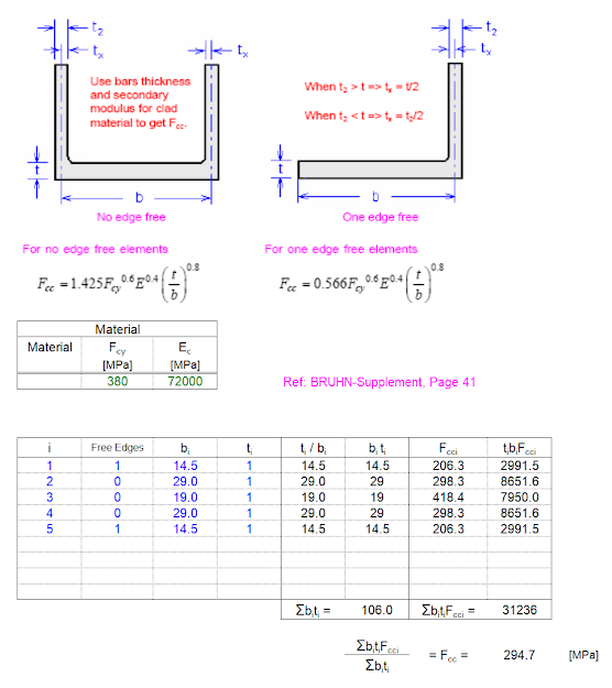
Figure-3 An example calculation
Don’t forget to check the technical notes section for more information on crippling.

Leave A Comment