Aircraft Structures – 2: The Fuselage of a Light Aircraft
Introduction:
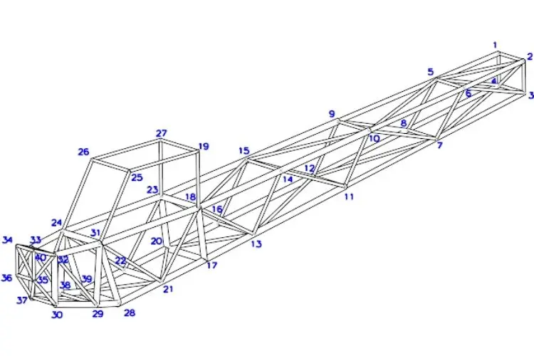
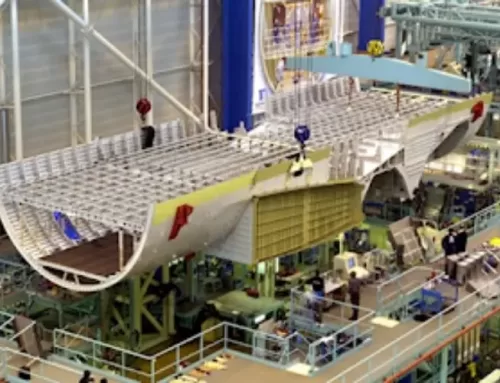
In this post, a light aircraft fuselage was designed from scratch in a 5-6 hour effort (see Figure-1) and the corner points (see Figure-3) were transferred to Excel, and connection tables were created to obtain the finite element solution mesh shown in Figure-4. After selecting appropriate loads and boundary conditions, analysis was performed, and each load on every element can be examined to optimize the structure of the fuselage.
Note: Whether or not structural analysis and optimization will be carried out depends on the level of interest and participation in the topic. I look forward to your contributions…
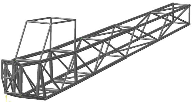
Figure-1: 3D fuselage geometry consisting of tubes.
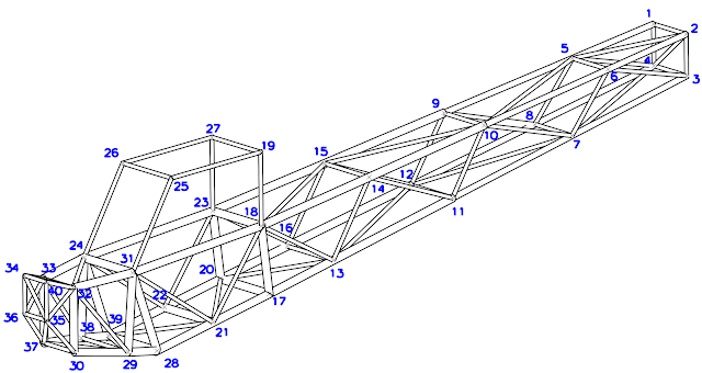
Figure-2: Isometric view of the fuselage and node points.
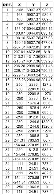
Figure-3: Coordinates of node points.

Figure-4: Finite element model created in Excel.


Leave A Comment